
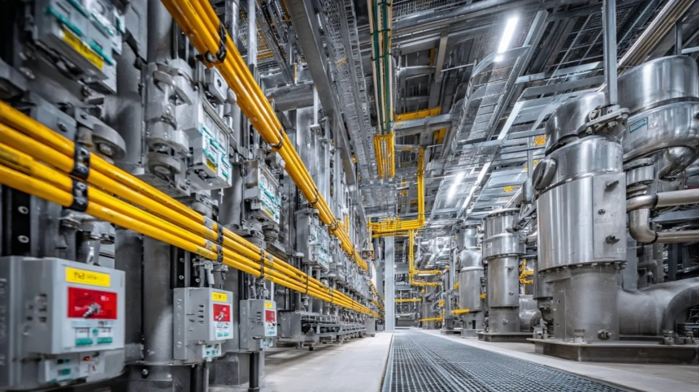
Earthing systems in Ex installations
During ATEX and DSEAR inspections, considerable attention is usually given to types of protection, temperature classes, EPL, equipment category, certificates and correct Ex marking. That is necessary. Yet one fundamental part of the electrical installation is often given too little attention: the earthing and equipotential bonding system.
In many industrial plants the power supply structure has developed over decades. Extensions, refurbishments, temporary supplies and local modifications may have resulted in TT, TN and sometimes IT arrangements existing close to each other. In an area where an explosive atmosphere may occur, that is not just an electrical engineering detail. It can directly influence fault currents, protective disconnection, touch voltages, sparking risk and the reliability of bonding between conductive parts.
The way an electrical system is earthed determines how fault currents return to the source and how quickly protective devices can disconnect a fault. This principle is described in the IEC 60364 series and, in the UK, through BS 7671 for low-voltage electrical installations. In ordinary electrical engineering this may appear to be a classic subject. In a hazardous area it becomes part of ignition source control.
Under the European ATEX workplace requirements, based on Directive 1999/92/EC, the employer must assess and control explosion risks at the workplace. In the UK, the same operational duty is reflected through DSEAR, the Dangerous Substances and Explosive Atmospheres Regulations 2002. Equipment placed on the EU market is covered by ATEX Directive 2014/34/EU, while in Great Britain equipment and protective systems for potentially explosive atmospheres fall under the Equipment and Protective Systems Intended for Use in Potentially Explosive Atmospheres Regulations 2016. These legal frameworks do not replace engineering judgement. They require the operator to demonstrate that ignition sources are prevented or effectively controlled.
That is exactly where earthing and bonding become critical.
In a TT system, the installation has its own earth electrode, independent of the source earthing arrangement. When an insulation fault occurs, the fault current returns to the source through the earth path. Because this path often has a relatively high impedance, residual current devices are normally essential to achieve reliable automatic disconnection. In industrial environments this can also mean that fault currents are less predictable and that potential differences may occur between separate conductive parts if bonding is not correctly designed and maintained.
In a TN-S system, the protective conductor and neutral conductor are separated throughout the installation. In the event of an insulation fault, the fault current returns to the transformer through a low-impedance protective path. This usually results in a higher fault current and faster operation of protective devices such as fuses or circuit breakers. For process installations with hazardous areas, a well-designed TN-S arrangement, combined with robust equipotential bonding, is often the most transparent and controllable solution.
Particular care is required where parts of an installation still contain TN-C arrangements. In a TN-C system, the protective function and neutral function are combined in a PEN conductor. A break or deterioration of the PEN conductor can cause exposed conductive parts or structural metalwork to rise to an unsafe potential. In a hazardous area, a potential difference between metallic parts can create unwanted sparking when contact is made or broken. For that reason, TN-C arrangements require very careful assessment in and around areas where explosive atmospheres may occur.
The installation requirements for explosive atmospheres, as set out in EN/IEC 60079-14, place strong emphasis on correct electrical installation design, selection and installation of equipment, including initial inspection. Earthing, equipotential bonding, protective conductors and the prevention of dangerous potential differences are not secondary issues. They are part of the basis on which electrical equipment can remain suitable for use in a hazardous area. EN/IEC 60079-17 then makes this a continuing responsibility by requiring inspection and maintenance to verify that the installation remains in a safe condition.
The standard does not simply prescribe one universal earthing system for every Ex installation. The correct solution depends on the supply system, protective devices, fault-loop impedance, bonding arrangement, installation age, environmental conditions and the hazardous area classification. However, in practice, a consistent and well-documented TN-S structure with reliable equipotential bonding is often the most robust arrangement for industrial process plants.
During inspections it is still common to find that the earthing system is barely described in the explosion protection documentation, the DSEAR assessment or the hazardous area inspection report. That is a weak point. The earthing and bonding system determines how fault currents behave, how quickly electrical faults are cleared and whether conductive parts remain at substantially the same potential.
Explosion safety is therefore not only about Ex markings, types of protection and temperature classes. Sometimes it starts with a basic electrical question:
How does the fault current return to the source — and are all conductive parts still bonded as the original Ex design assumed?
https://exquintia.com/
#ATEX #DSEAR #ExplosionSafety #HazardousAreas #ElectricalEngineering #Earthing #Bonding #IEC60364 #BS7671 #IEC60079 #ProcessSafety #IndustrialSafety #AssetIntegrity #Exquintia